Forward kinematics

 Clash Royale CLAN TAG#URR8PPP

An articulated six DOF robotic arm uses forward kinematics to position the gripper.
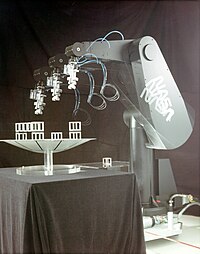
The forward kinematics equations define the trajectory of the end-effector of a PUMA robot reaching for parts.
Forward kinematics refers to the use of the kinematic equations of a robot to compute the position of the end-effector from specified values for the joint parameters.[1]
The kinematics equations of the robot are used in robotics, computer games, and animation. The reverse process that computes the joint parameters that achieve a specified position of the end-effector is known as inverse kinematics.
Contents
1 Kinematics equations
2 Link transformations
2.1 Kinematics equations revisited
2.2 Denavit-Hartenberg matrix
3 Computer animation
4 See also
5 References
Kinematics equations
The kinematics equations for the series chain of a robot are obtained using a rigid transformation [Z] to characterize the relative movement allowed at each joint and separate rigid transformation [X] to define the dimensions of each link. The result is a sequence of rigid transformations alternating joint and link transformations from the base of the chain to its end link, which is equated to the specified position for the end link,
- [T]=[Z1][X1][Z2][X2]…[Xn−1][Zn],displaystyle [T]=[Z_1][X_1][Z_2][X_2]ldots [X_n-1][Z_n],!
![[T] = [Z_1][X_1][Z_2][X_2]ldots[X_n-1][Z_n],!](https://wikimedia.org/api/rest_v1/media/math/render/svg/bf95be75044e9ef0f222808f03ab979f013f3315)
where [T] is the transformation locating the end-link. These equations are called the kinematics equations of the serial chain.[2]
Link transformations
In 1955, Jacques Denavit and Richard Hartenberg introduced a convention for the definition of the joint matrices [Z] and link matrices [X] to standardize the coordinate frame for spatial linkages.[3][4] This convention positions the joint frame so that it consists of a screw displacement along the Z-axis
- [Zi]=TransZi(di)RotZi(θi),displaystyle [Z_i]=operatorname Trans _Z_i(d_i)operatorname Rot _Z_i(theta _i),
![[Z_i]=operatorname Trans_Z_i(d_i)operatorname Rot_Z_i(theta _i),](https://wikimedia.org/api/rest_v1/media/math/render/svg/acd112611a35f4af4eb7cbc7b1d146640e544675)
and it positions the link frame so it consists of a screw displacement along the X-axis,
- [Xi]=TransXi(ai,i+1)RotXi(αi,i+1).displaystyle [X_i]=operatorname Trans _X_i(a_i,i+1)operatorname Rot _X_i(alpha _i,i+1).
![[X_i]=operatorname Trans_X_i(a_i,i+1)operatorname Rot_X_i(alpha _i,i+1).](https://wikimedia.org/api/rest_v1/media/math/render/svg/dc6862b8d910326bb871a9beb5229d78eeb40afd)
Using this notation, each transformation-link goes along a serial chain robot, and can be described by the coordinate transformation,
- i−1Ti=[Zi][Xi]=TransZi(di)RotZi(θi)TransXi(ai,i+1)RotXi(αi,i+1),displaystyle ^i-1T_i=[Z_i][X_i]=operatorname Trans _Z_i(d_i)operatorname Rot _Z_i(theta _i)operatorname Trans _X_i(a_i,i+1)operatorname Rot _X_i(alpha _i,i+1),
![^i-1T_i=[Z_i][X_i]=operatorname Trans_Z_i(d_i)operatorname Rot_Z_i(theta _i)operatorname Trans_X_i(a_i,i+1)operatorname Rot_X_i(alpha _i,i+1),](https://wikimedia.org/api/rest_v1/media/math/render/svg/19be395db0e2494e6f9d17bb8f8967799e938c1a)
where θi, di, αi,i+1 and ai,i+1 are known as the Denavit-Hartenberg parameters.
Kinematics equations revisited
The kinematics equations of a serial chain of n links, with joint parameters θi are given by[5]
- [T]=0Tn=∏i=1ni−1Ti(θi),displaystyle [T]=^0T_n=prod _i=1^n^i-1T_i(theta _i),
![[T]=^0T_n=prod _i=1^n^i-1T_i(theta _i),](https://wikimedia.org/api/rest_v1/media/math/render/svg/db41854357836e8b97260b217048122712eef46e)
where i−1Ti(θi)displaystyle ^i-1T_i(theta _i)


The matrices associated with these operations are:
- TransZi(di)=[10000100001di0001],RotZi(θi)=[cosθi−sinθi00sinθicosθi0000100001].displaystyle operatorname Trans _Z_i(d_i)=beginbmatrix1&0&0&0\0&1&0&0\0&0&1&d_i\0&0&0&1endbmatrix,quad operatorname Rot _Z_i(theta _i)=beginbmatrixcos theta _i&-sin theta _i&0&0\sin theta _i&cos theta _i&0&0\0&0&1&0\0&0&0&1endbmatrix.

Similarly,
- TransXi(ai,i+1)=[100ai,i+1010000100001],RotXi(αi,i+1)=[10000cosαi,i+1−sinαi,i+100sinαi,i+1cosαi,i+100001].displaystyle operatorname Trans _X_i(a_i,i+1)=beginbmatrix1&0&0&a_i,i+1\0&1&0&0\0&0&1&0\0&0&0&1endbmatrix,quad operatorname Rot _X_i(alpha _i,i+1)=beginbmatrix1&0&0&0\0&cos alpha _i,i+1&-sin alpha _i,i+1&0\0&sin alpha _i,i+1&cos alpha _i,i+1&0\0&0&0&1endbmatrix.

The use of the Denavit-Hartenberg convention yields the link transformation matrix, [i-1Ti] as
- i−1Ti=[cosθi−sinθicosαi,i+1sinθisinαi,i+1ai,i+1cosθisinθicosθicosαi,i+1−cosθisinαi,i+1ai,i+1sinθi0sinαi,i+1cosαi,i+1di0001],displaystyle operatorname ^i-1T_i=beginbmatrixcos theta _i&-sin theta _icos alpha _i,i+1&sin theta _isin alpha _i,i+1&a_i,i+1cos theta _i\sin theta _i&cos theta _icos alpha _i,i+1&-cos theta _isin alpha _i,i+1&a_i,i+1sin theta _i\0&sin alpha _i,i+1&cos alpha _i,i+1&d_i\0&0&0&1endbmatrix,

known as the Denavit-Hartenberg matrix.
Computer animation
The forward kinematic equations can be used as a method in 3D computer graphics for animating models.
The essential concept of forward kinematic animation is that the positions of particular parts of the model at a specified time are calculated from the position and orientation of the object, together with any information on the joints of an articulated model. So for example if the object to be animated is an arm with the shoulder remaining at a fixed location, the location of the tip of the thumb would be calculated from the angles of the shoulder, elbow, wrist, thumb and knuckle joints. Three of these joints (the shoulder, wrist and the base of the thumb) have more than one degree of freedom, all of which must be taken into account. If the model were an entire human figure, then the location of the shoulder would also have to be calculated from other properties of the model.
Forward kinematic animation can be distinguished from inverse kinematic animation by this means of calculation - in inverse kinematics the orientation of articulated parts is calculated from the desired position of certain points on the model. It is also distinguished from other animation systems by the fact that the motion of the model is defined directly by the animator - no account is taken of any physical laws that might be in effect on the model, such as gravity or collision with other models.
See also
- Inverse kinematics
- Kinematic chain
- Robot control
- Mechanical systems
- Robot kinematics
References
^ Paul, Richard (1981). Robot manipulators: mathematics, programming, and control : the computer control of robot manipulators. MIT Press, Cambridge, Massachusetts. ISBN 978-0-262-16082-7..mw-parser-output cite.citationfont-style:inherit.mw-parser-output qquotes:"""""""'""'".mw-parser-output code.cs1-codecolor:inherit;background:inherit;border:inherit;padding:inherit.mw-parser-output .cs1-lock-free abackground:url("//upload.wikimedia.org/wikipedia/commons/thumb/6/65/Lock-green.svg/9px-Lock-green.svg.png")no-repeat;background-position:right .1em center.mw-parser-output .cs1-lock-limited a,.mw-parser-output .cs1-lock-registration abackground:url("//upload.wikimedia.org/wikipedia/commons/thumb/d/d6/Lock-gray-alt-2.svg/9px-Lock-gray-alt-2.svg.png")no-repeat;background-position:right .1em center.mw-parser-output .cs1-lock-subscription abackground:url("//upload.wikimedia.org/wikipedia/commons/thumb/a/aa/Lock-red-alt-2.svg/9px-Lock-red-alt-2.svg.png")no-repeat;background-position:right .1em center.mw-parser-output .cs1-subscription,.mw-parser-output .cs1-registrationcolor:#555.mw-parser-output .cs1-subscription span,.mw-parser-output .cs1-registration spanborder-bottom:1px dotted;cursor:help.mw-parser-output .cs1-hidden-errordisplay:none;font-size:100%.mw-parser-output .cs1-visible-errorfont-size:100%.mw-parser-output .cs1-subscription,.mw-parser-output .cs1-registration,.mw-parser-output .cs1-formatfont-size:95%.mw-parser-output .cs1-kern-left,.mw-parser-output .cs1-kern-wl-leftpadding-left:0.2em.mw-parser-output .cs1-kern-right,.mw-parser-output .cs1-kern-wl-rightpadding-right:0.2em
^ J. M. McCarthy, 1990, Introduction to Theoretical Kinematics, MIT Press, Cambridge, Massachusetts.
^ J. Denavit and R.S. Hartenberg, 1955, "A kinematic notation for lower-pair mechanisms based on matrices." Trans ASME J. Appl. Mech, 23:215–221.
^ Hartenberg, R. S., and J. Denavit. Kinematic Synthesis of Linkages. New York: McGraw-Hill, 1964 on-line through KMODDL
^ Jennifer Kay. "Introduction to Homogeneous Transformations & Robot Kinematics" (PDF). Retrieved 2010-09-11.
^ Learn About Robots. "Robot Forward Kinematics". Retrieved 2007-02-01.
